Catalyst Regenerator Flow Diagram Continuous Regeneration Ca
Catalyst processes simulated Schematic representation of continuous catalytic regeneration [7 Question 21: when operating with one or more catalyst coolers on a
Schematic diagram showing step by step procedure involved in catalyst
Catalyst cooler in fcc regenerator designs: (a) internal cooler, (b Catalytic reforming flowchart (semi-regenerative) Catalyst regeneration market will see strong expansion through forecast
Schematic representation for the catalyst test system and used reactor
Fluid catalytic cracking plantRegeneration catalytic representation schematic Reactor fcc regenerator catalystSchematic depiction of the fluid catalytic cracking (fcc) process.
Elevation view of the port dickson reactor–regenerator section. thisContinuous regeneration catalyst catalytic reforming process refining petroleum figure psu education edu Schematic of the flow reactor used to measure catalyst performanceCatalyst evaluation.

Schematic diagram of flow-cell configuration for homogeneous catalyst
Flow charts collection n°3Continuous catalyst regeneration Schematic diagram of catalytic reactor systemFluid catalytic cracking catalyst regeneration intensification.
Modular construction of catalyst-regen unit saves time, costsCatalytic reforming regenerative flowchart Patent us7153479Continuous catalyst regeneration.

Process flow diagram of the catalyst evaluation set-up
Continuous catalyst regenerationFluid catalytic cracking unit fcc modern chemical factory equipment oil Lnkd catalyticSchematic diagram of flow-cell configuration for homogeneous catalyst.
Regenerator reactor vessel dickson clearly catalyst internals major countercurrent proprietary flowContinuous catalyst regeneration Scaleup of the catalyst regenerator.External view of the fcc catalyst regenerator reactor showing a good.

Continuous reforming catalytic regeneration
Catalyst regeneration expansion forecastFluid catalytic cracking process in oil refinery the petro solutions Fluid catalytic cracking catalyst regeneration intensificationCatalytic cracking process, fouling, and cleaning methods.
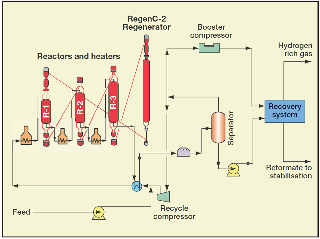
Fcc cracking catalytic fluid process reactor regenerator depictionRfcc catalyst petroleum arrangement typical handbook Catalyst regeneration continuous reforming process catalytic semi regenerative reactor petroleum gas refining heater h2 figureReactor catalyst measure.

Process flow diagram of a continuous catalytic regeneration reforming
Fcc unit. (a) schematic diagram of a simplified set up; (b) industrialCatalyst reactor test Catalytic reformingSchematic diagram showing step by step procedure involved in catalyst.
Catalyst unit regeneration refinery gas regen modular costs saves construction time section ogj its-catalyst cooler process arrangement for a typical rfcc unit (handbook Catalyst regenerator coolerProcess flow diagram for catalyst reusability study..

(a) schematic of catalyst system showing the major processes being
Reactor catalytic .
.